2.1 Module 2 Learning Outcomes
This module gives you the electrical basics needed to wire safely, size correctly, and troubleshoot faster.
By the end of this module, you will be able to:
- Explain the core electrical terms used in solar and battery systems (V, A, W, kW, Wh, kWh)
- Apply the key formulas used in installer work (Ohm’s Law + power and energy equations)
- Understand how series and parallel wiring changes voltage and capacity
- Make better decisions on cable sizing, terminations and protection devices
- Understand earthing and bonding basics for safe, stable systems
- Identify common electrical installation errors before they cause failures
2.2 The Core Electrical Terms You Must Be Comfortable With
These are the terms you will use every day when sizing, wiring, testing, commissioning, and fault-finding energy systems.
Understanding what each term means—and how they relate to one another is essential for designing safe, efficient, and reliable installations.
Before we look at more advanced concepts, let's first understand the five fundamental electrical principles that form the foundation of every battery and solar system.
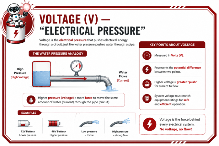
Voltage (V) — “Electrical Pressure”
Voltage is the electrical pressure that drives electricity through a system.
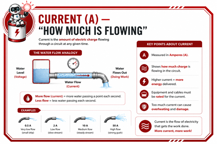
Current (A) — “How Much is Flowing”
Current is the amount of electricity flowing through a conductor.
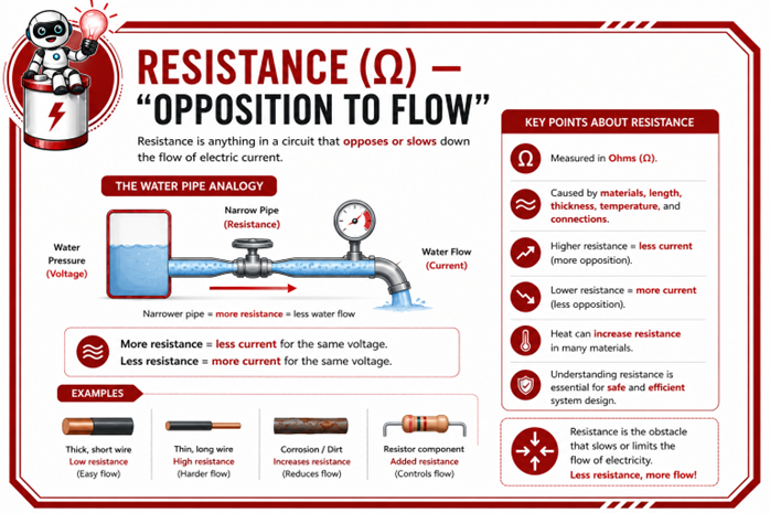
Resistance (Ω) — “Opposition to Flow”
Resistance is anything that restricts or opposes the flow of energy.
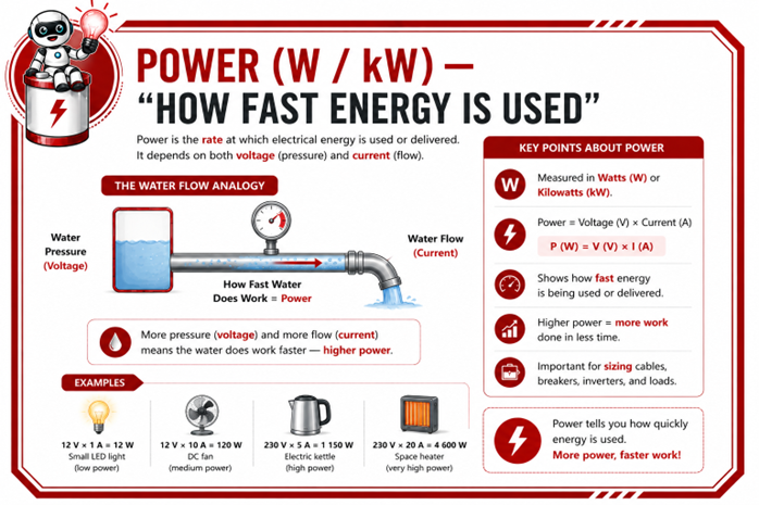
Power (W / kW) — “How Fast Energy is Used”
Power is how much electricity is being used or supplied at a specific moment.
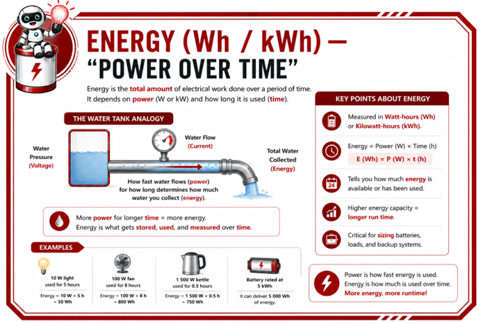
Energy (Wh / kWh) — “Power Over Time”
Energy is the total amount of electricity used or stored over a period of time .
Summary:
Understanding the relationship between voltage, current, resistance, power, and energy is essential for correctly sizing systems, selecting equipment, troubleshooting faults, and ensuring safe operation.
Remember:
Power (kW) = what is happening right now
Energy (kWh) = what happens over time
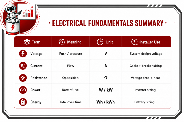
The summary below provides a quick-reference guide to the key electrical terms.
2.3 AC vs DC in Practice
This section explains what AC and DC do in the system, why they behave differently, and what that means for wiring, protection and fault finding.
In every system, you’re dealing with two completely different electrical environments:
🔌 AC (Alternating Current):Household power and comes from Eskom or generator.
🔋 DC (Direct Current):Comes from solar panels and batteries.
🔋 DC (Direct Current) — “High Current, High Consequence”
DC flows in one direction. Simple in theory… but in practice, it demands respect.
In our systems, DC is used for:
- PV strings feeding the inverter
- Battery charge and discharge
- High-current battery cables
- DC breakers and isolators
Here’s the important part, DC does not forgive mistakes.
- Polarity matters — reverse it and you can damage equipment instantly.
- DC arcs don’t “let go” easily like AC does. If something sparks, it can keep sparking.
- High battery currents mean heat becomes a real issue if cables or lugs are undersized.
- Small mistakes (loose lug, wrong torque, bad crimp) show up quickly under load.
🔌 AC (Alternating Current) — Where Compliance and Stability Matter
AC changes direction 50 times per second (50 Hz). That constant switching is what allows it to travel long distances efficiently and power homes safely.
On your installs, AC is used for:
- Inverter output to essential loads
- Grid input
- Generator connection (where applicable)
Key Principle
For the same amount of power, increasing the system voltage reduces the amount of current flowing through the system.
This is one of the main reasons why modern residential systems commonly use 48V battery architectures, while larger commercial and industrial systems increasingly use high-voltage (HV) battery systems.
Understanding the Different System Voltages
Different voltage architectures are used for different applications. The choice of system voltage depends on factors such as the amount of power required, the size of the installation, installation cost, scalability, and overall system efficiency.
As energy demands increase, systems generally move from lower voltages to higher voltages to reduce current, improve efficiency, and simplify installation.
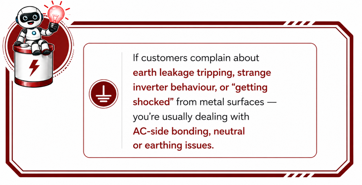
- The inverter must match the grid’s voltage and frequency before connecting.
- Neutral and earth must be handled correctly — this is where many nuisance trips start.
- Earth leakage placement matters.
- Protection must comply with SANS wiring standards.
AC brings a different set of considerations:
The Inverter — The Electrical Traffic Controller
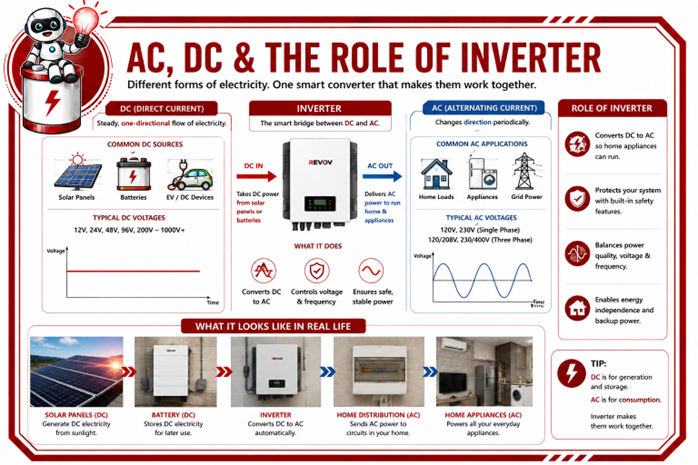
The inverter is one of the most important components in any battery and solar system. While many people think its only job is to convert DC electricity into AC electricity, it actually performs a much more important role.
The inverter sits between two completely different electrical environments:
On the DC side, it receives electricity generated by the solar panels and stored in the batteries.
On the AC side, it supplies electricity to the loads and interacts with the utility grid.
The inverter continuously monitors the system and makes intelligent decisions about how energy should flow. It controls:
- Where power is supplied from
- When batteries should charge or discharge
- When to prioritise solar, battery, or grid power
- How energy is distributed to the loads
- When to activate protection functions to keep the system safe
Think of the inverter as a traffic controller standing at a busy intersection. It constantly decides where electricity should come from, where it should go, and how to keep everything moving safely
and efficiently. Without the inverter managing these energy pathways, the different parts of the system would not be able to work together effectively.
What This Looks Like in Real Life
What You Should Be Checking on Site
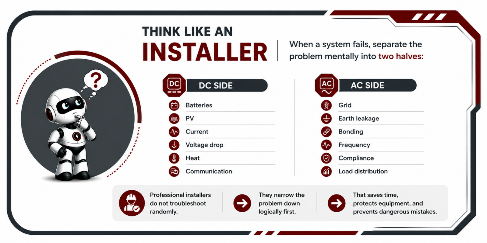
When you’re troubleshooting, think in two halves. If you can mentally separate AC and DC while
diagnosing a fault, your troubleshooting becomes much faster.
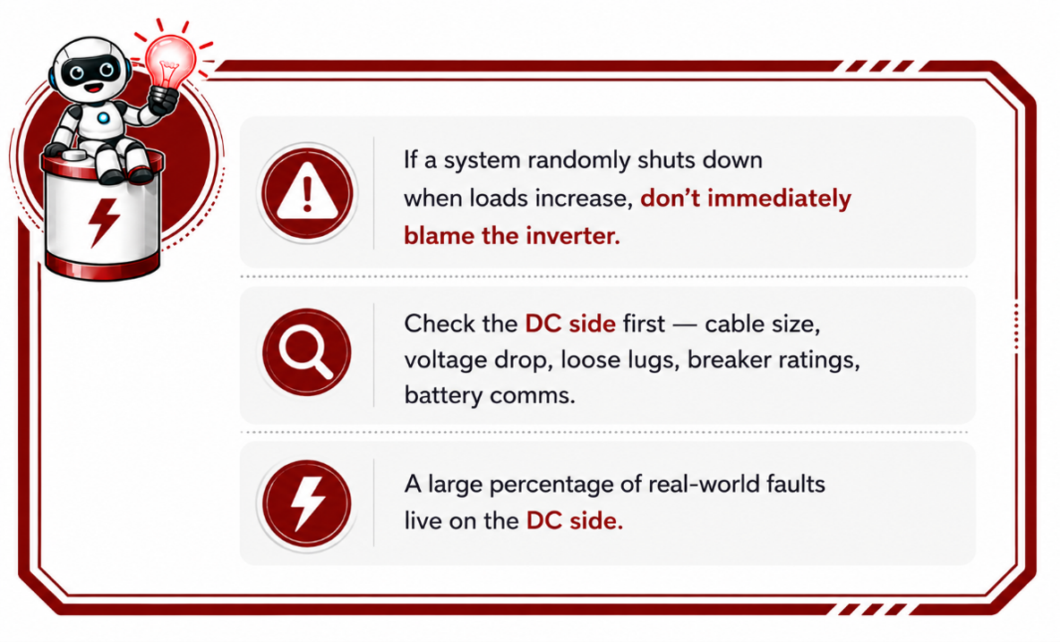
DC is where you deal with heat, polarity, voltage drop and high current - DC Side Checks:
- Polarity correct
- Cable size correct
- Lugs properly crimped and torqued
- DC breaker rated for DC
- PV voltage within limits
- Battery communication working
AC is where you deal with compliance, synchronisation, bonding and protection rules - AC Side Checks:
- Essential and non-essential loads separated correctly
- Neutral correctly installed
- Earth leakage correctly placed
- Grid settings configured properly
- Earthing and bonding done to standard
2.4 Understanding Battery System Voltage Architectures
As energy systems become larger and more powerful, selecting the correct system voltage
becomes one of the most important design decisions an installer will make. The operating voltage
of a system influences its performance, efficiency, safety, and scalability.
Understanding why different voltage architectures are used will help you design better systems, select the correct equipment, and troubleshoot installations more effectively.
System voltage directly affects:
- current flow
- cable size
- heat generation
- efficiency
- inverter compatibility
- battery configuration
- system cost
- installation complexity
Understanding why systems operate at different voltages is an important step towards thinking like a professional installer.
What Does “System Voltage” Mean?
System voltage refers to the normal operating voltage of the battery and inverter system. It
determines how electricity is transferred between the batteries, inverter, and other system components
Common system voltages include:
- 12V
- 24V
- 48V
- High-voltage (HV) battery systems
The inverter and battery must always operate at compatible voltages for the system to function safely and correctly.
Think of voltage as the electrical pressure that pushes electricity through a circuit. The higher the voltage, the less current is required to deliver the same amount of power.
This principle is one of the key reasons why modern battery systems increasingly operate at higher voltages.
Why Current Matters So Much in Battery Systems
While voltage is important, current is often the biggest challenge in battery installations. Most
installation problems are not caused by voltage itself, but by excessive current flowing through cables, connectors, and electrical equipment.
High current can result in:
- heat generation
- voltage drop
- cable losses
- overheated terminals
- breaker stress
- increased fire risk
This is why installers must understand the relationship between:
- Voltage
- Current
- Power
The Relationship Between Voltage, Current, and Power
These three electrical concepts are directly connected. When designing a battery system, changing one of these values affects the others.
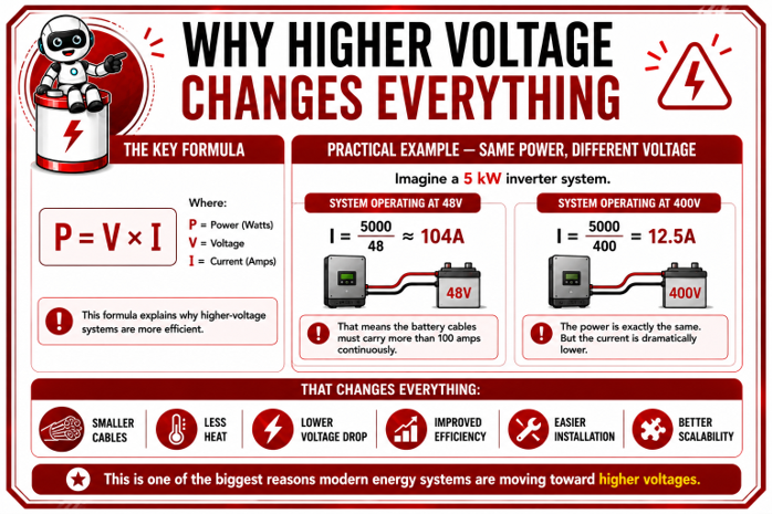
The relationship is shown by the following formula:Where:
- P = Power (Watts)
- V = Voltage (Volts)
- I = Current (Amps)
This formula tells us that power is equal to voltage multiplied by current.
However, for installers, the most important lesson is not the formula itself—it is understanding what happens when the system voltage changes.
Why Higher Voltage Means Lower Current
Imagine two systems that both need to deliver exactly the same amount of power (5 kW).
The only difference is their operating voltage.
The comparison below demonstrates how increasing the system voltage dramatically reduces the amount of current required to deliver the same power.
What Does This Comparison Show?
Both systems produce exactly the same amount of power—5 kW.
However, because the operating voltages are different, the amount of current flowing through the system is very different.
- A 48V system requires approximately 104A of current to deliver 5 kW.
- A 400V system requires only 12.5A of current to deliver the same 5 kW.
Although the power delivered is identical, the higher-voltage system requires significantly less current.
This reduction in current has several important advantages for installers:
- Smaller cable sizes
- Less heat generation
- Reduced voltage drop
- Improved system efficiency
- Easier installation
- Better scalability
This simple comparison illustrates one of the most important principles in battery and energy storage system design:
For the same amount of power, increasing the system voltage reduces the amount of current flowing through the system.
This is one of the main reasons why modern residential systems commonly use 48V battery architectures, while larger commercial and industrial systems increasingly use high-voltage (HV) battery systems.
Understanding the Different System Voltages
Now that you understand why increasing the system voltage reduces current, let's look at how this principle is applied in real-world energy storage systems.
Different voltage architectures are used for different applications. The choice of system voltage depends on factors such as the amount of power required, the size of the installation, installation cost, scalability, and overall system efficiency.
As energy demands increase, systems generally move from lower voltages to higher voltages to reduce current, improve efficiency, and simplify installation.
The following sections introduce the four most common battery system voltage architectures and explain where each is typically used, together with their advantages and limitations.
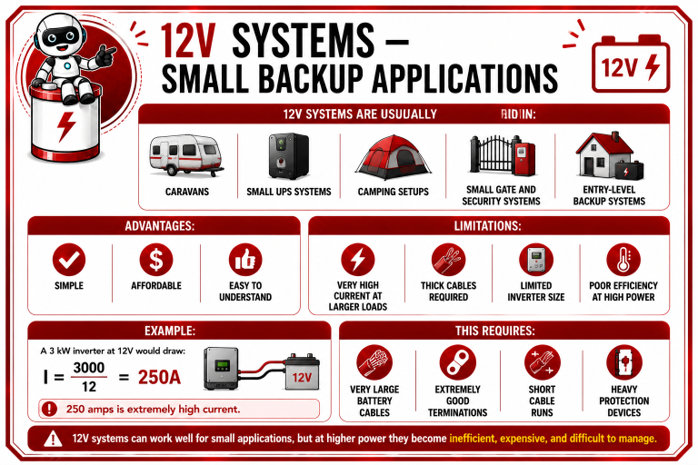
12V Systems – Small Backup Applications
Although 12V systems are simple and cost-effective, they become less practical as power requirements increase because the current rises significantly.
This means larger cables, heavier protection devices, and greater installation challenges.
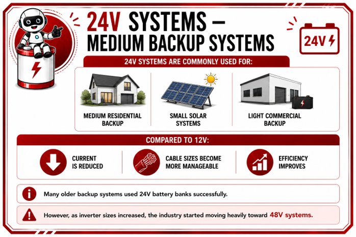
24V Systems – Medium Backup Systems
Moving from 12V to 24V immediately reduces the current required for the same power output. This makes cable sizing more manageable and improves overall system efficiency.
While 24V systems are still used in some residential and light commercial applications, most modern lithium systems have progressed to 48V architectures.
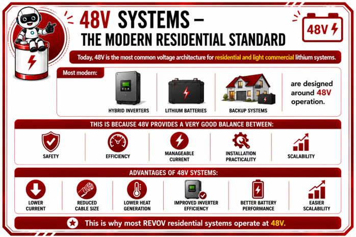
48V Systems – The Modern Residential Standard
Today, 48V has become the preferred voltage architecture for most residential and light commercial lithium battery systems.
It provides an excellent balance between safety, efficiency, manageable current levels, installation practicality, and future expansion, making it the standard for most modern hybrid energy systems.
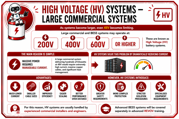
High Voltage (HV) Systems – Large Commercial Installations
As energy requirements continue to increase, even 48V systems become impractical due to the very high currents required.
High Voltage (HV) battery systems solve this by operating at much higher voltages, dramatically reducing current and making large commercial and industrial energy storage systems more efficient and scalable.
Because of the higher voltages involved, these systems require specialised equipment, additional protection measures, and experienced installers.
What This Means for Installers
Understanding system voltage architecture is about much more than knowing the difference between 12V, 24V, 48V and high-voltage (HV) systems.
As an installer, the operating voltage influences almost every design and installation decision you make.
System voltage directly affects:
- Cable sizing
- Breaker and fuse selection
- Inverter compatibility Battery configuration
- Installation layout
- Voltage drop
- Heat generation
- System efficiency
- Future scalability
As energy demands have increased, the industry has steadily moved towards higher-voltage systems because they deliver the same amount of power with significantly lower current. This allows installers to design systems that are more efficient, easier to install, more scalable, and better suited to modern residential and commercial energy requirements.
Understanding these principles will help you select the correct system architecture, design safer installations, and explain to customers why different applications require different voltage systems.
Remember: Choosing the correct system voltage is not simply about selecting a battery—it is about designing an energy system that is safe, efficient, reliable, and capable of meeting the customer's current and future energy needs.

Series & Parallel Connections Explained
One battery is often not enough to meet the voltage or energy requirements of a solar or backup system. As systems become larger, multiple batteries are connected together to create a battery bank that can deliver the required voltage, storage capacity, and runtime.
Depending on the system requirements, batteries are connected in either series or parallel.
The type of connection determines whether the system gains:
- Higher voltage
- More energy storage
- Longer backup time
- Greater current capability
Understanding the difference between these two connection methods is essential for correctly designing, installing, and expanding battery systems.
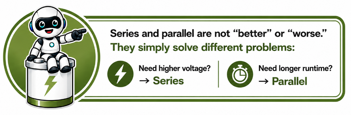
Remember: There are only two ways to connect batteries together—series or parallel. Each changes the electrical characteristics of the battery bank in a different way.
Series Connection – Voltage Adds,Capacity in Ah stays the same!,
E.g. A 12V 100Ah battery bank made by connecting four 3.2V 100Ah cells in series.
A series connection is used when the system requires a higher operating voltage.
In a series connection, the batteries are connected:
- positive to negative
- like a chain
The voltage increases, but the storage capacity (Ah) stays the same.
Think of it like adding more pressure to a water pipe. The pressure increases, allowing the system to operate at a higher voltage, while the amount of stored energy in each battery (Ah) remains unchanged.
Series connections are commonly used when:
- the inverter requires a higher DC voltage (24V, 48V, etc.)
- lower current is required
- improved system efficiency is desired
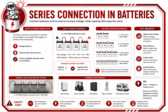
After studying the diagram, notice that every additional battery increases the system voltage, while the battery capacity remains the same.
This allows installers to build battery banks that meet the voltage requirements of different inverter systems without changing the individual battery capacity.
Parallel Connection – Capacity Adds, Voltage Stays the Same
E.g. 2x48V 100Ah batteries in parallel = 48V 200Ah = 9.6KWH
A parallel connection is used when the system already operates at the correct voltage but requires additional energy storage and longer backup time.
In a parallel connection, all positives connect together and all negatives connect together.
The voltage stays the same, but the storage capacity increases.
Imagine two water tanks feeding the same house. The water pressure stays the same, but: .
After reviewing the diagram, notice that adding batteries in parallel increases the total battery capacity (Ah) and available runtime, while the operating voltage remains unchanged.
Imagine you have the same equipment: a small inverter and two identical 12V batteries.
Using the same two batteries, you can build two completely different battery banks.
- there is now twice as much water available
- the house can run longer before the tanks are empty
Battery systems work in much the same way.
Parallel connections are commonly used when:
- longer backup time is required
- additional battery capacity is needed
- the inverter already operates at the correct battery voltage
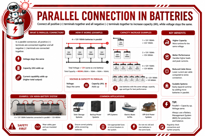
After reviewing the diagram, notice that adding batteries in parallel increases the total battery capacity (Ah) and available runtime, while the operating voltage remains unchanged.
Real-World Example – One Setup, Two Ways
Understanding the theory behind series and parallel connections is important, but professional installers must also know when to use each configuration in practice.
Imagine you have the same equipment:
- A small inverter
- Two identical 12V batteries
Although the equipment is exactly the same, the way you connect the batteries completely changes how the system operates.
The following example demonstrates how choosing either a series or parallel connection produces two very different battery systems, each designed for a different purpose.
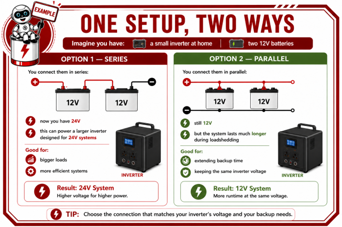
Using the same two batteries, you can build two completely different battery banks.
Option 1 – Series Connection
Connecting the batteries in series increases the battery bank voltage from 12V to 24V, while the battery capacity (Ah) remains the same.
This configuration is used when: the inverter requires a higher DC voltage, lower current is preferred, or larger loads need to be supplied efficiently.
- The inverter requires a higher DC voltage
- lower current is preferred
- larger loads need to be supplied efficiently
Option 2 – Parallel Connection
Connecting the batteries in parallel keeps the battery bank at 12V, but doubles the available battery capacity.
This configuration is used when:
- longer backup time is required
- more stored energy is needed
- the inverter already operates at the correct battery voltage
The Key Lesson
The batteries themselves have not changed.
The inverter has not changed.
Only the way the batteries are connected has changed.
Yet the result is two completely different battery systems.
This is why installers must never connect batteries based on guesswork or convenience. The correct connection method is always determined by:
- the inverter's voltage requirements
- the customer's backup requirements
- the required runtime
- and the overall system design
Remember: A battery bank should always be designed to match both the inverter specifications and the customer's energy requirements—not simply by adding more batteries.
Comparing Series and Parallel Connections
Although both methods connect multiple batteries together, they achieve completely different objectives.
A
series connection increases the system voltage while maintaining the same battery capacity.
A
parallel connection increases the battery capacity and available runtime while maintaining the same system voltage.
Understanding this difference is one of the most important skills for designing battery banks correctly.
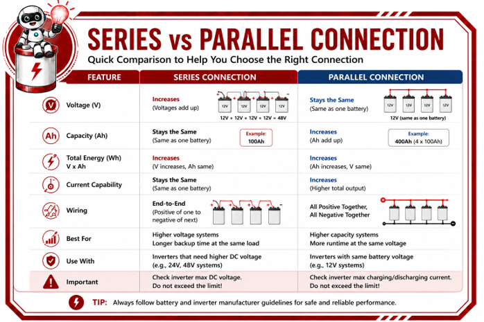
Study the comparison carefully and note the key differences between the two connection methods.
As an installer, this information will help you determine the correct battery configuration based on the inverter requirements and the customer's backup needs.
2.5 Electrical Components
Every electrical system needs to:
- move power,
- control power
- protect equipment
- protect people
- manage voltage and current
- switch things on and off
- and communicate between devices
Electrical components make all this possible.
Without the correct components, electricity would simply flow uncontrolled from the batteries to
the equipment-which can lead to:
- overheating
- damaged equipment
- poor performance
- fires
- system failures
- and serious safety risks
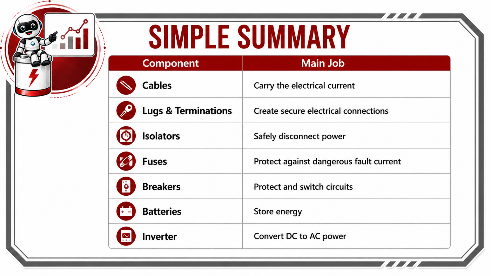
A good battery or solar system is not only about the batteries. The cables, lugs, isolators, fuses, breakers, and connections are just as important.
Think of the system like the plumbing in a building:
- The battery is the water tank
- The cables are the pipes
- The isolators and breakers are the valves
- The fuses are the emergency safety devices
- The lugs and terminations are the joints connecting everything together
If any one of these parts is poor quality or installed incorrectly, the whole system can fail.
Understanding the Key Electrical Components
Every electrical component in a battery and solar system has a specific purpose. Some components carry electricity, others control it, while others protect the system and the people using it.
As an installer, it is essential to understand not only what each component is, but also why it is used, how it works, and the role it plays in ensuring a safe, reliable, and efficient installation.
The following diagrams introduce the most common electrical components found in battery and solar systems. As you work through each one, pay particular attention to:
- The purpose of the component
- Where it is used in the system
- Why it is important
- What could happen if it is incorrectly selected or installed
Although these components may appear simple on their own, together they form the foundation of every safe and reliable energy storage system.
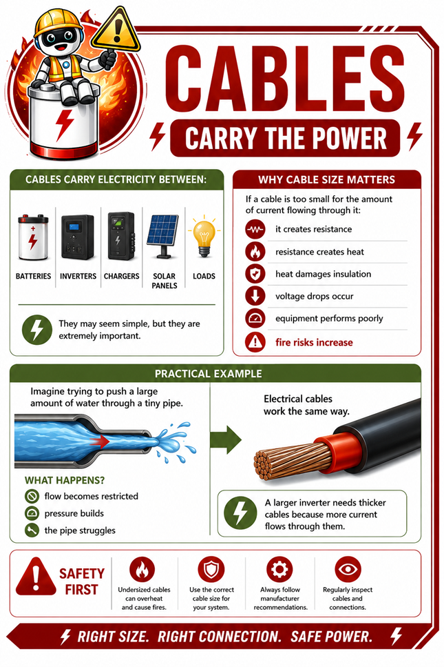
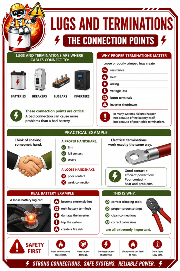
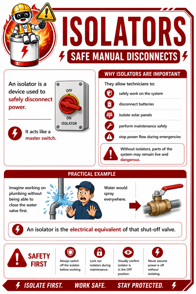
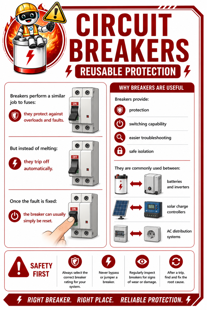
A battery system is only as strong as its weakest connection.
Even the best battery can fail if:
- cables are undersized
- lugs are loose
- breakers are incorrect
- fuses are missing
- or isolators are not installed properly.
Good electrical design is about:
- safety
- reliability
- efficiency,
- and long equipment life.
2.6 Earthing & Bonding — The Safety Backbone
Earthing and bonding are two of the most important safety principles in any battery and solar installation. Although they perform different functions, they work together to protect people, equipment, and property by reducing the risk of electric shock, equipment damage, and fire.
Correct earthing and bonding help protect:
- people
- equipment
- buildings
- batteries
- and inverters.
Without proper earthing and bonding:
- electric shocks can occur
- equipment can become damaged
- systems can behave unpredictably
- lightning damage can become worse
- faults may not trip correctly
- and fire risks increase.
A simple way to understand the difference is:
- Earthing gives dangerous electricity a safe path to the ground
- Bonding keeps metal parts at the same electrical level so they cannot become dangerous
Both are essential for a safe and compliant electrical installation. One does not replace the other—they work together to protect the entire system.
Understanding Earthing & Bonding
Although earthing and bonding are closely related, they perform different safety functions within an electrical installation. Understanding the difference is essential for every installer
The following diagrams explain what earthing is, what bonding is, why each is important, and how they work together to create a safer battery and solar system.
As you review each diagram, pay attention to:
- the purpose of earthing and bonding,
- how they protect people and equipment,
- where they are used within the system,
- and what can happen if they are omitted or installed incorrectly.
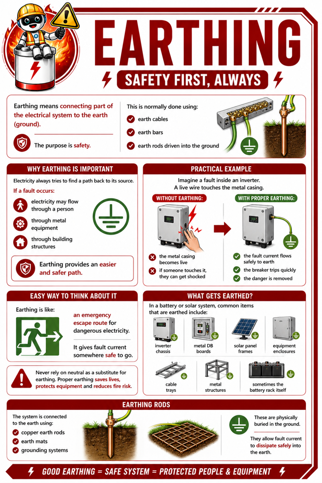
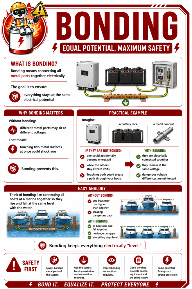
Although earthing and bonding perform different functions, they are most effective when used together.
- Earthingprovides a safe path for fault current to flow into the ground.
- Bonding ensures exposed metal parts remain at the same electrical potential.
Together they help protective devices operate correctly, minimise electric shock hazards, reduce the risk of fire, and improve the overall safety of the installation.
Remember: A properly designed battery or solar system is not only efficient—it is also safe. Correct earthing and bonding are fundamental requirements for every professional installation.
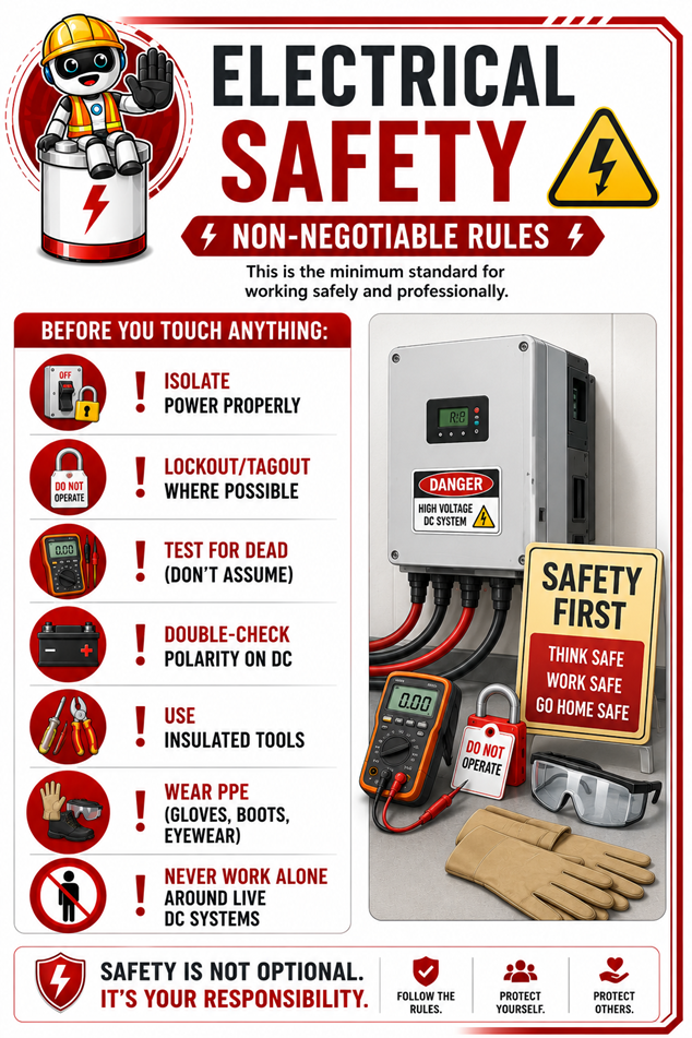
2.7 Electrical Safety — Non-Negotiable Rules
Electrical safety is non-negotiable because electricity is invisible, extremely powerful, and can cause serious injury, death, fires, or catastrophic equipment damage in seconds if handled incorrectly.
Unlike many other hazards, you often do not get a warning before something goes wrong. A loose connection, incorrect polarity, missing fuse, poor earthing, or accidental contact with live conductors can instantly create dangerous heat, electric shock, arc flash, or system failure.
In battery and solar systems especially, large amounts of stored energy are always present, even when grid power is off, which means safe isolation, proper PPE, correct tools, testing procedures, and compliant installation practices are absolutely essential.
Good electrical safety is not about slowing the job down, it is about ensuring that everyone goes home safely, equipment remains protected, and systems operate reliably for years to come.
2.8 Real-World Installer Scenarios (What Can Go Wrong + How to Fix It)
Up to this point, you have learned the theory behind electrical components, cable sizing, battery connections, and system protection. While understanding the theory is essential, professional installers must also recognise what happens when these principles are not applied correctly.
Many system faults are not caused by defective equipment; they are caused by poor installation practices.
Something as simple as using the wrong cable size, making a poor crimp, or leaving a loose terminal can lead to overheating, nuisance trips, damaged equipment, expensive call-backs, and even serious safety hazards.
The following examples are based on real installation scenarios that installers encounter every day. Each example demonstrates:
- what went wrong,
- why it happened,
- what problems it caused,
- and how the issue can be prevented or corrected
As you work through each example, think beyond simply fixing the fault. Ask yourself why it occurred in the first place and what could have been done during installation to prevent it.
Remember:
Most installation problems are preventable. Good installers do not just fix faults; they install systems correctly the first time.
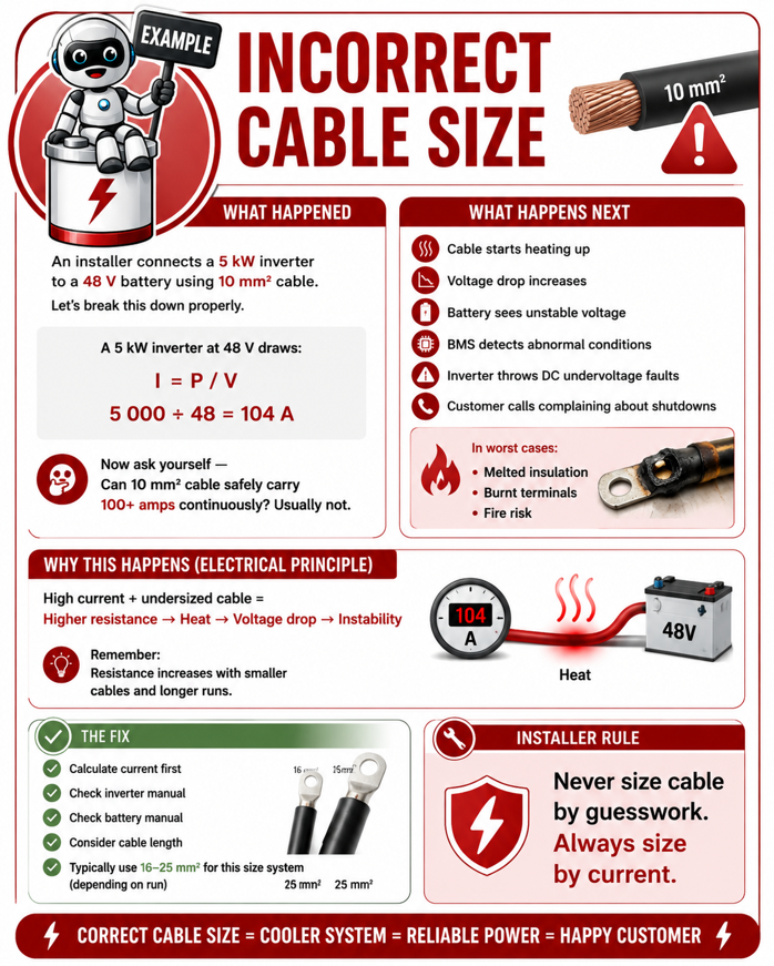
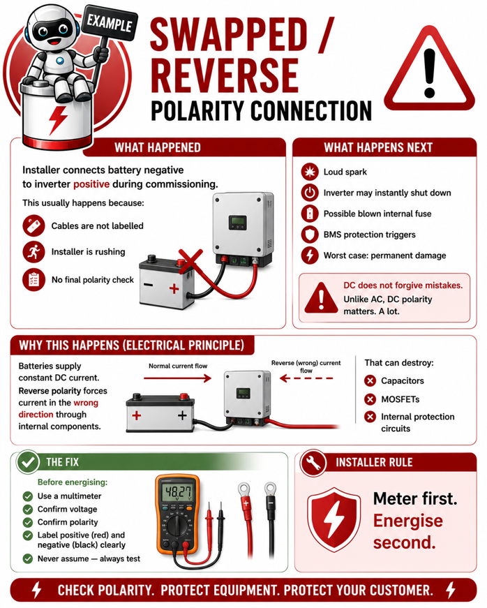
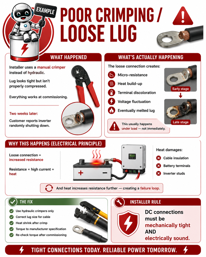
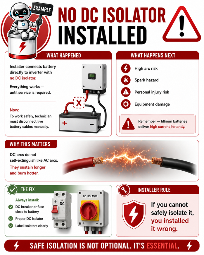
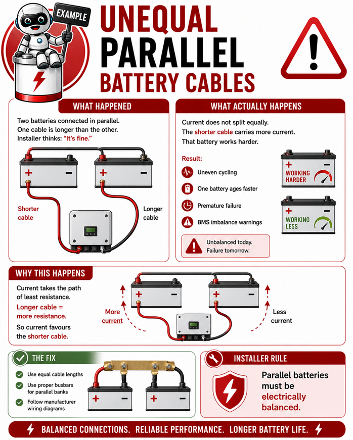
Every fault shown in this section has one thing in common: it could have been prevented during installation.
It could have been prevented during installation.
Professional installers understand that system reliability is not determined only by the quality of the batteries or inverter—it is determined by the quality of the installation
A correctly sized cable, a properly crimped lug, a securely tightened connection, and careful attention to detail may seem like small tasks, but together they make the difference between a system that operates reliably for years and one that generates repeated faults and customer complaints.
Remember: the best fault is the one that never happens because the installation was done correctly the first time.
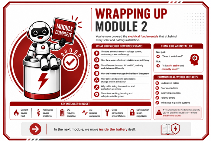
Wrapping Up Module 2
📚 Continue to Module 2 Assessment Quiz (Electrical Fundamentals)
You’ve reached the end of Module 2 (Electrical Fundamentals).